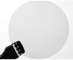
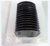
PAM-XIAMEN grows high quality Gallium Antimonide (GaSb) single crystal ingots. We have round, saw cut, lap and polish GaSb wafers and can supply an epi-ready surface quality. GaSb crystal is a compound formed by 6N pure Ga and Sb element and is grown by Liquid Encapsulated Czochralski ( LEC ) method with EPD < 1000 cm -3 . GaSb crystal has high uniformity of electrical parameters and low defect density , suitable for MBE or MOCVD epitaxial growth . We have "epi ready " GaSb products with wide choice in exact or off orientation , low or high doped concentration and good surface finish . Please contact us for more product information . GaSb( Gallium Antimonide) wafer PAM-XIAMEN grows high quality Gallium Antimonide (GaSb) single crystal ingots. We have round, saw cut, lap and polish GaSb wafers and can supply an epi-ready surface quality. GaSb crystal is a compound formed by 6N pure Ga and Sb element and is grown by Liquid Encapsulated Czochralski ( LEC ) method with EPD < 1000 cm -3 . GaSb crystal has high uniformity of electrical parameters and low defect density , suitable for MBE or MOCVD epitaxial growth . We have "epi ready " GaSb products with wide choice in exact or off orientation , low or high doped concentration and good surface finish . Please contact us for more product information . 1)2",3"GaSb wafer Orientation:(100)±0.5° Thickness(μm):500±25;600±25 Type/Dopant:P/undoped;P/Si;P/Zn Nc(cm-3):(1~2)E17 Mobility(cm2/V ·s):600~700 Growth Method:CZ Polish:SSP 2)2"GaSb wafer Orientation:(100)±0.5° Thickness(μm):500±25;600±25 Type/Dopant:N/undoped;P/Te Nc(cm-3):(1~5)E17 Mobility(cm2/V ·s):2500~3500 Growth Method:LEC Polish:SSP 3)2"GaSb wafer Orientation:(111)A±0.5° Thickness(μm):500±25 Type/Dopant:N/Te;P/Zn Nc(cm-3):(1~5)E17 Mobility(cm2/V ·s):2500~3500;200~500 Growth Method:LEC Polish:SSP 4)2"GaSb wafer Orientation:(111)B±0.5° Thickness(μm):500±25;450±25 Type/Dopant:N/Te;P/Zn Nc(cm-3):(1~5)E17 Mobility(cm2/V ·s):2500~3500;200~500 Growth Method:LEC Polish:SSP 5)2"GaSb wafer Orientation:(111)B 2deg.off Thickness(μm):500±25 Type/Dopant:N/Te;P/Zn Nc(cm-3):(1~5)E17 Mobility(cm2/V ·s):2500~3500;200~500 Growth Method:LEC Polish:SSP Relative products: InAs wafer InSb wafer InP wafer GaAs wafer GaSb wafer GaP wafer Gallium Antimonide (GaSb) can be supplied as wafers with as-cut, etched or polished finishes and are available in a wide range of carrier concentration, diameter and thickness. GaSb material presents interesting properties for single junction thermophotovoltaic (TPV) devices. GaSb: Te single crystal grown with Czochralski (Cz) or modified Czo- chralski (Mo-Cz) methods are presented and the problem of Te homogeneity discussed. As the carrier mobility is one of the key points for the bulk crystal, Hall measurements are carried out. We present here some complementary developments based on the material processing point of view: the bulk crystal growth, the wafer preparation, and the wafer etching. Subsequent steps after these are related...
Xiamen Powerway Advanced Material Co., Ltd (PAM-XIAMEN) offers InSb crystal wafer up to 3" in diameter that are grown by a modified Czochralski method from highly purified, zone refined polycrystalline ingots. 1)2"InSb Orientation:(100) Type/Dopant:N/undoped Diameter:50.8mm Thickness:300±25µm;500um Nc:<2E14a/cm3 Polish:SSP 2)2"InSb Orientation:(100) Type/Dopant:N/Te Diameter:50.8mm Carrier Concentration: 0.8 – 2.1 x 1015 cm-3 Thickness:450+/- 25 um;525±25µm EPD < 200 cm-2 Polish:SSP 3)2"InSb Orientation:(111) + 0.5° Thickness:450+/- 50 um Type/Dopant:N/undoped Carrier Concentration: < 5 x 10^14 cm-3 EPD < 5 x 103 cm-2 Surface roughness: < 15 A Bow/Warp: < 30 um Polish:SSP 4)2"InSb Orientation:(111) + 0.5° Type/Dopant:P/Ge Polish:SSP 5)2"InSb Thickness:525±25µm, Orientation:[111A]±0.5° Type/Dopant:N/Te Ro=(0.020-0.028)Ohmcm, Nc=(4-8)E14cm-3/cc, u=(4.05E5-4.33E5)cm²/Vs, EPD<100/cm², Mobility:4E5cm2/Vs One side edge; In(A) Face: Chemically-mechanically final polished to 0.1µm (Final Polish), Sb(B) Face: Chemically-mechanically final polished to <5µm (Lasermark), NOTE: Nc and Mobility are at 77ºK. Polish:SSP;DSP 6)2" GaSb Thickness:525±25µm, Orientation:[111B]±0.5°, Type/Dopant:P/undoped;N/undoped Polish:SSP;DSP Surface Condition and other Specification Indium Antimonide (InSb) wafer can be offered as wafers with as-cut, etched or polished finishes with wide range of doping concentration and thickness. The wafer could be high quality epi-ready finishing. Orientation Specification Wafer surface orientations are supplied to an accuracy of +/- 0.5 degrees using a triple axis X-Ray diffractometer system. Substrates can also be supplied with very precise misorientations in any direction from the growth plane. The available orientaiton could be (100),(111), (110) or other orientation or mis degree. Packaging condition Polished wafer:individually sealed in two outer bags in inert atmosphere. Cassette shipments are available if required). As-cut Wafer:Cassette shipment. (Glassine bag available on request). Words Wiki Indium antimonide (InSb) wafer is a crystalline compound made from the elements indium (In) and antimony (Sb). It is a narrow-gap semiconductormaterial from the III-V group used in infrared detectors, including thermal imaging cameras, FLIR systems, infrared homing missile guidancesystems, and in infrared astronomy. The indium antimonide detectors are sensitive between 1–5 µm wavelengths. Indium antimonide was a very common detector in the old, single-detector mechanically scanned thermal imaging systems. Another application is as a terahertz radiationsource as it is a strong photo-Dember emitter. Relative products: InAs wafer InSb wafer InP wafer GaAs wafer GaSb wafer GaP wafer If you are more interesting in insb wafer,Please send emails to us;sales@powerwaywafer.com,and visit our website:www.powerwaywafer.com.
Highlights •N-polar InAlN thin films were grown on GaN substrates by molecular beam epitaxy. •Surface morphology transitioned from quasi-3D to step-flow at high temperature. •Indium saturation was observed for increasing indium flux at high temperature. •Increased aluminum flux helped increase indium incorporation efficiency. •N-polar InAlN films with 0.19 nm rms roughness were demonstrated. Abstract N-polar InAlN thin films were grown by plasma-assisted molecular beam epitaxy on freestanding GaN substrates under N-rich conditions. Indium and aluminum fluxes were varied independently at substrate temperatures below and above the onset of thermal desorption of indium. At low temperatures, the InAlN composition and growth rate are determined by the group-III fluxes. With increasing substrate temperature, the surface morphology transitions from quasi-3D to a smooth, 2D morphology at temperatures significantly above the onset of indium loss. At higher temperatures, we observe increased indium evaporation with higher indium fluxes and a suppression of indium evaporation with increased aluminum flux. The final optimized InAlN thin film results in step-flow morphology with rms roughness of 0.19 nm and high interfacial quality. Keywords A1. Crystal morphology; A1. Desorption; A3. Molecular beam epitaxy; B1. Nitrides; B2. Semiconducting ternary compounds Source:Sciencedirect For more information, please visit our website:www.powerwaywafer.com, send us email at sales@powerwaywafer.com .
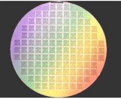
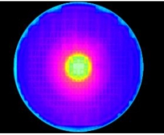
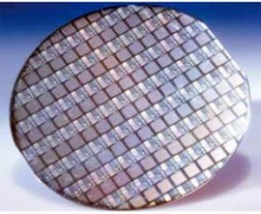
The International Technology Roadmap for Semiconductors (ITRS) identifies production test data as an essential element in improving design and technology in the manufacturing process feedback loop. One of the observations made from the high-volume production test data is that dies that fail due to a systematic failure have a tendency to form certain unique patterns that manifest as defect clusters at the wafer level. Identifying and categorising such clusters is a crucial step towards manufacturing yield improvement and implementation of real-time statistical process control. Addressing the semiconductor industry’s needs, this research proposes an automatic defect cluster recognition system for semiconductor wafers that achieves up to 95% accuracy (depending on the product type). Keywords Semiconductor wafer fabrication; Defect cluster classification; Recognition; Feature extraction Source:Sciencedirect For more information, please visit our website:www.powerwaywafer.com, send us email at sales@powerwaywafer.com .
Highlights •GaSb p–i–n diodes were grown on Si and GaAs using interfacial misfit (IMF) arrays. •Transmission electron microscopy images revealed arrays of 90° misfit dislocations. •Threading dislocation densities of around View the MathML source were found in each case. •Lower dark currents and higher quantum efficiency was found for growth on GaAs. Abstract GaSb p–i–n photodiodes were grown on GaAs and Si, using interfacial misfit arrays, and on native GaSb. For the samples grown on GaAs and Si, high-resolution transmission electron microscopy images revealed interface atomic periodicities in agreement with atomistic modeling. Surface defect densities of ~View the MathML source were measured for both samples. Atomic force microscopy scans revealed surface roughnesses of around 1.6 nm, compared with 0.5 nm for the sample grown on native GaSb. Dark current and spectral response measurements were used to study the electrical and optoelectronic properties of all three samples. Keywords A1 Atomic force microscopy; A1 Defects; A1 High-resolution X-ray diffraction; A1 Interfaces; A3 Molecular beam epitaxy; B1 Antimonides Source:Sciencedirect For more information, please visit our website:www.powerwaywafer.com, send us email at sales@powerwaywafer.com .
We quantified the size and concentration of Te inclusions along the lateral- and the growth-directions of a ∼6 mm-thick wafer cut axially along the center of a CdZnTe ingot. We fabricated devices, selecting samples from the center slice outward in both directions, and then tested their response to incident X-rays. We employed, in concert, an automated IR transmission microscopic system and a highly collimated synchrotron X-ray source that allowed us to acquire and correlate comprehensive information on Te inclusions and other defects to assess the material factors limiting the performance of CdZnTe detectors. Keywords CdZnTe; Detectors; Te inclusions; Dislocations; Pipes; IR transmission Source:Sciencedirect For more information, please visit our website:www.powerwaywafer.com, send us email at sales@powerwaywafer.com .
Highlights •A recessed structure was used on the GaAs/Si solar cells to reduce the current path. •The associated series resistance was reduced by a recessed structure. •The carrier recombination loss was improved due to pyramid-like recessed structure. In this study, epitaxial layers of GaAs-based solar cells were grown on Si substrates using a molecular beam epitaxial system. The pyramid-like via hole recessed electrode structure was fabricated on the back side of the Si substrate to improve the performance of the resulting solar cells. Since the current path was effectively reduced by the via hole recessed structure, the associated series resistance and the carrier recombination loss of the resulting GaAs/Si solar cells were decreased. Consequently, the conversion efficiency enhancement of 21.8% of the GaAs/Si solar cells with the via hole recessed structure was obtained due to the improvement in the short-circuit current density and the fill factor compared with the conventional GaAs/Si solar cells. Keywords GaAs/Si solar cells; Low-temperature atomic layer epitaxy method; Molecular beam epitaxial system; Hole recessed structure Source:Sciencedirect For more information, please visit our website:www.powerwaywafer.com, send us email at sales@powerwaywafer.com .
Highlights •The validity of comparing DC and RF HTOL test results is a key issue in reliability testing. •We investigate whether DC and RF self heating, and therefore channel temperature, are equivalent. •For this purpose, an experimentally validated electrothermal model has been developed. •Channel temperature is found to be equivalent during RF and DC operation at typical operating voltages. Abstract Channel temperature is a key parameter for accelerated life testing in GaN HEMTs. It is assumed that self-heating is similar in RF and DC operations and that DC test results can be applied to RF operation. We investigate whether this assumption is valid by using an experimentally calibrated, combined electrical and thermal model to simulate Joule heating during RF operation and compare this to DC self-heating at same power dissipation. Two cases are examined and the implications for accelerated life testing are discussed: typical (30 V) and high (100 V) drain voltages. Keywords GaN; HEMT; Reliability; Temperature; Simulation; Thermography; RF Source:Sciencedirect For more information, please visit our website:www.powerwaywafer.com, send us email at sales@powerwaywafer.com .
 Contact Information
 luna@powerwaywafer.compowerwaymaterial@gmail.com
  +86-592-5601 404