Crystal wafer(SiC wafer,gan wafer,gaas wafer,ge wafer,CZT wafer,AlN wafer,Si wafer)
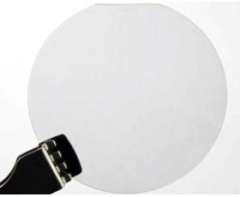
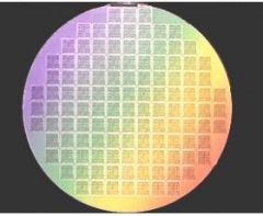
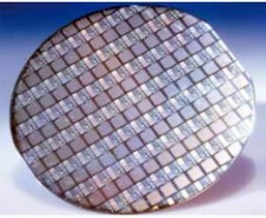
A wafer, also called a slice or substrate, is a thin slice of semiconductor material, such as a crystalline silicon, used in electronics for the fabrication of integrated circuits and in photovoltaics for conventional, wafer-based solar cells. The wafer serves as the substrate for microelectronic devices built in and over the wafer and undergoes many microfabrication process steps such as doping or ion implantation, etching, deposition of various materials, and photolithographic patterning. Finally the individual microcircuits are separated (dicing) and packaged.
XiamenPowerway Advanced Material Co.,Ltd offers wide range crystal wafer as follows:
1)SiC crystal wafer:2”,3”,4”
Orientation :0°/4°±0.5°
Single Crystal 4H/6H
Thickness: (250 ± 25) μm, (330 ± 25) μm,(430 ± 25) μm
Type:N/SI
Dopant:Nitrogen/V
Resistivity (RT): 0.02 ~ 0.1 Ω·cm/>1E5 Ω·cm
FWHM: A<30 arcsec B/C/D <50 arcsec
Packaging:Single wafer box or multi wafer box
2)GaN crystal wafer:1.5",2”,3",4"6"
Free-standing (gallium nitride) GaN Substrate
Orientation:C-axis(0001)+/-0.5°
Thickness:350um
Resistivity(300K): <0.5Ω·cm >10^6Ω·cm
Dislocation Density:<5x10^6cm-2
TTV:<=15um
BOW:<=20um
Surface Finish:Front Surface:Ra<0.2nm.Epi-ready polished
3)Germanium crystal wafer: 2”,3”,4”
Orientation :+/- 0.5 °
Type / Dopant : N / Sb; P / Ga
Diameter : 100 mm
Thickness : 525 +/- 25 um
Resistivity : 0.1 ~ 40 ohm-cm
Primary flat location :+/-0.5 degree
Primary flat length : 32.5 +/-2.5 mm
Front surface : Polished
Back surface : Etched
Edge surface finishing : cylindrical ground
Surface roughness ( Ra ) : <=5A
EPD : <= 5000 cm-2
Epi ready : yes
Package : Single wafer container
4)GaAs crystal wafer: 2”,3”,4”,6”
Thickness:220~500m
Conduction Type:SC/n-type
Growth Method:VGF
Dopant:Silicon/Zn
Orientation:(100)20/60/150 off (110)
Resistivity at RT:(1.5~9)E-3 Ohm.cm
Packaging:Single wafer container or cassette
2" LT-GaAs
Thickness:1-2um or 2-3um
Resistivity(300K):>108 Ohm-cm
Polishing:Single side polished
(GaAs)Gallium Arsenide Wafers for LED/LD/Microelectronics/ Applications
5)CZT crystal wafer(15*15±0.05mm,25*25±0.05mm,30*30±0.05mm)
Orientation (111)B,(211)B
Thickness:
Doped:Undoped
Resistivity:≥1MΩ.cm
EPD≤1x10⁵/cm3
Double side polished
6)AlN crystal wafer:2”
7)Silicon crystal wafer: 2”,3”,4”,6”,8”
8)LiNbO3 crystal wafer: 2”,3”,4”,6”
9)LiTaO3 crystal wafer: 2”,3”,4”,6”
10)InAs,InP crystal wafer: 2”,3”,4”
11)Othercrystal wafer with small size:ZnO, MgO, YSZ, STO, LSAT, TiO2, LAO, Al2O3,SrTiO3, LaAlO3
Standard wafer sizes
Silicon wafers are available in a variety of diameters from 25.4 mm (1 inch) to 300 mm (11.8 inches). Semiconductor fabrication plants (also known as fabs) are defined by the diameter of wafers that they are tooled to produce. The diameter has gradually increased to improve throughput and reduce cost with the current state-of-the-art fab using 300 mm, with a proposal to adopt 450 mm.Intel, TSMC and Samsung are separately conducting research to the advent of 450 mm "prototype" (research) fabs, though serious hurdles remain.
2-inch (51 mm), 4-inch (100 mm), 6-inch (150 mm), and 8-inch (200 mm) wafers
1-inch (25 mm)
2-inch (51 mm). Thickness 275 µm.
3-inch (76 mm). Thickness 375 µm.
4-inch (100 mm). Thickness 525 µm.
5-inch (130 mm) or 125 mm (4.9 inch). Thickness 625 µm.
150 mm (5.9 inch, usually referred to as "6 inch"). Thickness 675 µm.
200 mm (7.9 inch). Thickness 725 µm.
300 mm (11.8 inch). Thickness 775 µm.
450 mm (17.7 inch). Thickness 925 µm (proposed).
Wafers grown using materials other than silicon will have different thicknesses than a silicon wafer of the same diameter. Wafer thickness is determined by the mechanical strength of the material used; the wafer must be thick enough to support its own weight without cracking during handling.
Cleaning, texturing and etching
Wafers are cleaned with weak acids to remove unwanted particles, or repair damage caused during the sawing process. When used for solar cells, the wafers are textured to create a rough surface to increase their efficiency. The generated PSG (phosphosilicate glass) is removed from the edge of the wafer in the etching.
Releative Products
crystal sapphire wafer
single crystal wafer
wafer crystal defects
piezo crystal wafers
single crystal silicon wafer
If you need more information about crytal wafer,
please visit our website: http://www.semiconductorwafers.net,
send us email at luna@powerwaywafer.com and powerwaymaterial@gmail.com
 Contact Information
 luna@powerwaywafer.compowerwaymaterial@gmail.com
  +86-592-5601 404